Labels
Extending Basic Disks on windows server 2003 using DISKPART.exe does not work.
To extend the basic disk with 3rd party tool using EXTPART. ExtPart is a small tool developed by dell Industries and which helps to extend disk on windows 2003 servers as follows
Usage:
extpart [volume size]
volume - the volume to extend. e.g. f:, g:, etc (only basic volumes)
size - the size in megabytes by which to extend the volume.
Example:
To extend the g: volume by 1 GB (1024 MB) use the following command:
extpart g: 1024
Download Link: http://www.dell.com/support/drivers/in/en/19/driverdetails?driverid=R64398
We solved the problem by doing the following:
1) Checked the FilterRunType of the NDIS driver in :
HKEY_LOCAL_MACHINE\SYSTEM\CurrentControlSet\Control\Network\{4d36e974-e325-11ce-bfc1-08002be10318}\{72891E7B-0A3D-4541-BDCB-3DA62E25B6A8}\Ndi
FilterRunType was set to 1 ---> Changed the value to 2;
2) Checked to see if "DefaultGateway" registry was in HKLM\System\CCS\Services\TCPIP\Parameters\Interfaces\<Our interface>
---> It was missing. So we added a new Multi-String value, called it "DefaultGateway", and added our default gateway (10.32.8.1).
In case you have multiple interfaces, please do the following:
Run the following Powershell script:
>> gwmi Win32_NetworkAdapter | ?{$_.PhysicalAdapter -eq "True" -and $_.NetEnabled -eq $True}
Note the DeviceID value of the adapter we are interested in;
Then, go to the following registry value:
HKEY_LOCAL_MACHINE\SYSTEM\CurrentControlSet\Control\Class\{4d36e972-e325-11ce-bfc1-08002be10318}\<DeviceID>\Linkage
Note the GUID under the RootDevice value;
Then go back to HKLM\System\CCS\Services\TCPIP\Parameters\Interfaces\<GUID> , and add the default gateway as instructed above.
3) Browsed to HKLM\System\CurrentControlSet\Control\network,
----> Deleted the "Config" registry value, after backing up the 'network' key
We rebooted the server: The issue was fixed, we added a static IP, subnet mask, Default GW, and primary and Secondary DNS TCP/IP info in the properties of the adapter, and they stuck.
We rebooted the server and tested several times.
We then made these changes on the other affected servers, and everything is back in order.
Creating an NLB Cluster
There are three key steps to creating an NLB cluster in Windows Server 2008:
- Install the NLB Feature into Server 2008 on each host that you will add to an NLB cluster.
- Use the New Cluster wizard to create the cluster and add the first host.
- Use the Add Host wizard to add one or more nodes to your cluster
Installing NLB in Server 2008
This is extremely easy. First you run Server Manager, and select Features from the tree and click on Add Features:

From the Add Features wizard just selects Network Load Balancing and click Next:

Finally from the Confirm Installation Selections click install:

After a few seconds, NLB will be installed on the first host. You need to repeat this installation on each host you plan to add to your NLB Cluster. Installing the NLB feature does NOT require a reboot, but removing it does.
Add another NIC for heart beat
Creating your NLB Cluster
Once NLB is installed, you create your cluster by first bringing up the NLB Cluster Manager:

The right clicks the Network Load Balancing cluster node in the left pane, and select New Cluster:

This brings up the first page of the New Cluster Wizard – here you select the first member of your cluster by adding the IP address or DNS name into the Host box:

This shows you the interfaces on this host that you can use for configuring a new cluster. Chose the interface and click Next:

This brings up the Host Parameters page, where you enter the IP address to be used for the cluster for the cluster, and then you click next:
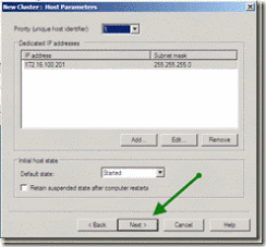
This brings up the Cluster IP address page. Here you add the address used by clients to connect to nodes in the cluster:

After adding the IP address, and clicking next, the New Cluster wizard displays the Cluster Parameters where you specify the cluster IP configuration and the cluster operation mode (and click next):

Leaving all the default for the port rules; by default its set to all ports with Single affinity, which is sticky. For more information on Port Rules

The Wizard then does the necessary configuration, resulting in a single node NLB cluster, shown in the NLB manager like this:

Adding Additional Nodes
A single node cluster is not much value, so you next need to add an additional node (or nodes). To add a node, you right click your newly created cluster and select Add Host to Cluster:

This brings up the Add Host to Cluster: Connect page where you specify the host to add, and the interface used in the cluster:

Next you specify the new host’s parameters:
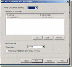
Then you get to update, in needed the cluster’s port rules:
![clip_image030[1] clip_image030[1]](http://lh3.ggpht.com/-kUo2Ov5eKJ0/UYAdmWEJ1XI/AAAAAAAAAGk/RrXtwaBMb4A/clip_image030%25255B1%25255D%25255B2%25255D.gif?imgmax=800)
Clicking next completes the wizard, resulting in a 2nd host in the cluster. As seen by NLB Manager:

- Make sure that both node’s status changes to "Converged"
- Make sure each node has a unique "host priority" ID
- Make sure each node is "started" under "initial host state"
- Make sure you see a "succeeded" message in the log window for the second node
BlueScreenView utility allows you to watch the blue screen crashes occurred in your system by reading and analyzing the MiniDump files created on every crash by the operating system. The MiniDump files are usually created under C:\WINDOWS\Minidump, unless the path was modified in the system failure settings of Windows.
In most systems, Windows is already configured to create these MiniDump files as the default system failure configuration.
However, if from some reason MiniDump files are not created in your system during a blue screen crash, you should follow the instructions below in order to configure Windows to create them.
For Windows XP:
- Right-click on the 'My Computer' icon and choose 'Properties'. Alternatively, you can also go to Control Panel and open the 'System' applet.
- In the opened window, click the 'Advanced' tab and then inside the 'Startup And Recovery' frame, click the 'Settings' button.
System Properties Window - In the opened 'Startup And Recovery' window, there is 'Write Debugging Information' section. You should set the combo-box in this section to 'Small memory dump', and then click 'ok' to confirm the change.
Startup And Recovery
- Go to the Control Panel, choose 'System And Security', and then click 'System', and then click the 'Advanced System Settings' link.
- In the opened window, click the 'Advanced' tab and then inside the 'Startup And Recovery' frame, click the 'Settings' button.
- In the opened 'Startup And Recovery' window, there is 'Write Debugging Information' section. You should set the combo-box in this section to 'Small memory dump', and then click 'ok' to confirm the change.
Windows Registry Editor Version 5.00
[HKEY_LOCAL_MACHINE\SYSTEM\CurrentControlSet\Control\CrashControl]
"CrashDumpEnabled"=dword:00000003
However, be aware that this Registry change affects the system only after reboot.
BlueScreenView scans all your minidump files created during 'blue screen of death' crashes, and displays the information about all crashes in one table. For each crash, BlueScreenView displays the minidump filename, the date/time of the crash, the basic crash information displayed in the blue screen (Bug Check Code and 4 parameters), and the details of the driver or module that possibly caused the crash (filename, product name, file description, and file version).
For each crash displayed in the upper pane, you can view the details of the device drivers loaded during the crash in the lower pane. BlueScreenView also mark the drivers that their addresses found in the crash stack, so you can easily locate the suspected drivers that possibly caused the crash.
Download links are on the bottom of this page
System Requirement:
BlueScreenView works with Windows XP, Windows Server 2003, Windows Server 2008, Windows Vista, Windows 7, and Windows 8, as long as Windows is configured to save minidump files during BSOD crashes.
Download BlueScreenView (in Zip file)
For more information : http://www.nirsoft.net/utils/blue_screen_view.html
old host copy:
1.remove all snapshots from vm
2.from old host to new host copy...
vm.vmdk
vm.vmsd
vm.vmx
vm.vmxf
3. take a snapshot of old vm (arrange that noone make updates to website during this time. all this data will be lost.)
4. from old to new copy vm-flat.vmdk (this will take the longest)
5. on new host add vm.vmx to inventory in datastore1 repository.
6. change new vm network card to "host only" network( "host only" is virtual switch with no nic.)
7.start up new vm.
8.select I_moved uuid from vsphere client.
9.install new vmware tools
10.check to see if vm is working as it should.
11.shutdown and upgrade vm hardware.
12. check again to make sure everything is working in vm.
13.shutdown old vm.
14.change New vm network seting to correct virtual switch.( I did this with vm still running to avoid the startup time)
Voila! Only about 30 seconds of downtime. This won't work if you need the delta from the old vm. all I lost was 90 minutes of weblogs.
This might seem kind of obvious to those with more experience but perhaps there are others like me that could use this list.
Downloading and installing the VMware Converter Enterprise plugin is much easier than downloading an installable application. To download and install the VMware Converter Enterprise plugin, open your VMware Infrastructure client (VI Client), go to Plugins on the toolbar and click Manage Plugins. From there, the window shown in Figure 1 will appear.
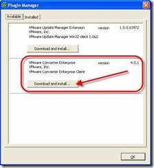
Figure 1: VI Client Plugin Manager
Just click Download and Install under VMware Converter Enterprise.
In a few seconds, you will be asked for your setup language and, what appears to be a regular application installation commences. Here are screenshots from that installation:

Figure 2: Converter Installation
After clicking install, you can monitor the program installation:
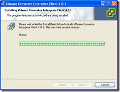
Figure 3: Converter Installation Progress
The installation only takes a few seconds. When done, you will be back at the plugin manager and you will see that the VMware Converter is installed.

Figure 4: Converter Plugin is installed
At this point, we are directed to the installed tab to enable the new plugin. I clicked on the installed tab, and found the Converter Enterprise client and clicked Enabled.
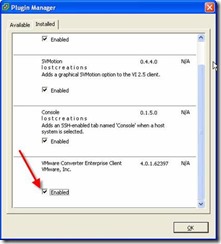
Figure 5: VMware Converter Enterprise Plugin Enabled
So how do we use the new plugin? Let’s find out.
Using the VMware Converter Enterprise Plugin
Once enabled, you will find that if you right-click on an ESX host system in the VI client, there will be a new option – Import Machine. This option is the result of the newly installed and enabled VMware Converter Enterprise.
Let’s say that we want to perform a P2V conversion of a Windows XP workstation into the VMware ESX Server Infrastructure. To do this, we would select the ESX Server that we want to import this new virtual machine to, right-click on the ESX host, and click import machine.
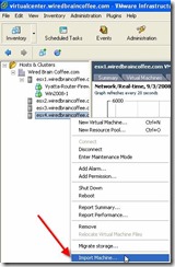
Figure 6: Importing a Virtual Machine with VMware Converter Enterprise
At this point, the 4 step import wizard will start.
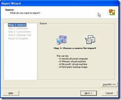
Figure 7: VMware Converter Import Wizard
You will be asked what the source of your import is. In our case we will import from a physical computer. However, we could also import from another VMware ESX Server, VMware Workstation, VMware Fusion, VMware Server, a VMware Consolidated Backup (VCB) image, or other third party virtual machine or backup.
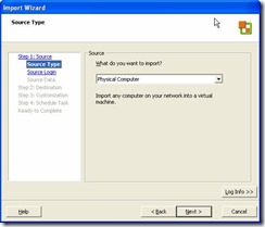
Figure 8: Source of system being converted
Next, you will be asked for the physical computer hostname and administrative credentials.
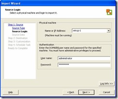
Figure 9: Physical computer hostname and administrative credentials
At this point, VMware Converter will connect to the physical computer and, very likely, as you if the VMware Converter Agent can be installed on that system.
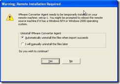
Figure 10: Remote Installation of VMware Converter Agent Required
You will need to click YES to continue.
The agent will be installed on the physical system, information about the disk volumes on the physical host will be retrieved, and you will be asked to review it.
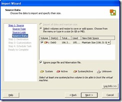
Figure 11: Reviewing disk information from physical computer
I chose to take the defaults an import the “C” drive from the physical host, ignoring the hibernation and page files.
Next , you will be shown the destination for the converted host system. As I originally selected “ESX4”, that was our destination.
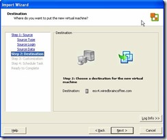
Figure 12: Destination of the newly converted virtual machine
You will be asked for the name of the new VM and where you want it located in the virtual machine inventory. I named this test machine “WIN-XP-1-P2V”.
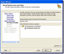
Figure 13: Virtual Machine name
Next, you will be asked what datastore you want to store the new virtual guest in and what virtual NIC cards you want connected to the new virtual machine (shown in Figure 14).
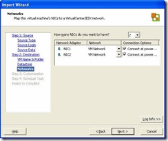
Figure 14: Selecting the virtual NIC cards to be connected to the converted VM
Then, you will be asked if you want to customize the new VM. I chose to install the VMware Tools and remove all Windows system restore checkpoints (in Figure 15).
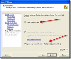
Figure 15: Customizing the imported virtual machine
You will be given the option to schedule the P2V conversion (in Figure 16).
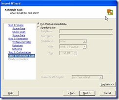
Figure 16: Ability to schedule the P2V Conversion
And finally, you will see the “ready to complete” (are you sure?) screen (in Figure 17). In this screen, you can choose to power on the VM after it is created.
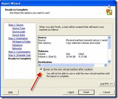
Figure 17: Ready to complete screen with power on option
After you click Finish, the P2V conversion (import) will begin. You will see its progress in the Recent Taskswindow.

Figure 18: Checking the progress of the P2V conversion
After some time (depending on the size of your physical computer hard drive that is being imported), the new VM will be created and available. Notice in Figure 19 the new “WINXP-1-P2V” VM that was created and how I successfully powered it on in Figure 20.
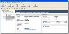
Figure 19: After P2V Conversion
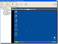
Figure 20: Successfully powered on VM created from VMware Converter Enterprise
A couple of things to watch out for:
- Uninstall as many drivers as possible from the physical computer that will be converted
- Make sure that your guest OS can reach fully qualified domain names on the network and that you are referring to it using FQDN
- Delete at much data on the physical computer as possible and use the option to transfer only the smallest amount of hard drive data as is required
- If cloning an already virtualized system, reinstalling your application, and just copying the data is not too difficult, then that is preferred to a full P2V conversion as you will end up with a “cleaner” VM (with less garbage from the previous OS installation, applications, and drivers)
Several boot loaders are used on Linux systems, such as the Grand Unified bootloader (GRUB) and theLinux Loader (LILO). ESX uses LILO as the boot loader and has system components that expect the presence of LILO as the boot loader, so don't replace LILO with another boot loader, or your server may experience problems. The configuration parameters for the bootloader are contained in /etc/lilo.conf in a human-readable format, but the actual bootloader is stored in a binary format on the boot sector of the default boot disk. This section explains the boot process of ESX Server, as well as how to load the VMkernel and configuration files.
High-Level Boot Process for ESX Server
-
BIOS is executed on the server.
-
BIOS launches LILO from the default boot drive.
-
LILO loads Linux Kernel for the Service Console.
-
The Service Console launches VMkernel.
-
MUI Server is started.
-
Virtual machines can then be launched by VMkernel and managed through MUI.
Brief Notes:
LILO - LILO stands for Linux boot loader. It will load the MBR, master boot record, into the memory, which tell the system which partition and hard drive to boot.
Grub - GRUB stands for GRand Unified Bootloader. It is a multiboot loader that can deal with many types of hardware and knows how to load a wide variety of UNIX-based operating systems as well as Windows.
MBR - A master boot record (MBR), or partition sector, is the 512-byte boot sector that is the first sector ("LBA Sector 0") of a partitioned data storage device such as a hard disk. (The boot sector of a non-partitioned device is a Volume Boot Record. These are usually different, although it is possible to create a record that acts as both; it is called a multi boot record.)
VMkernal -
VMkernel is a POSIX-like operating system developed by VMware. The VMkernel is the liaison between virtual machines (VMs) and the physical hardware that supports them. VMware calls VMkernel a microkernel because it runs on bare metal, directly on VMware ESX hosts. The VMkernal is responsible for allocating memory, scheduling CPUs and providing other hardware abstraction and operating system (OS) services.
Prerequisites
§ Version 7.0 or later of the Presentation Server Client/XenApp Plugin for 32-bit Windows is required on the system where the tool is launched.
§ The msstdfmt.dll and comdlg32.ocx files must be registered on the system (if they have not been registered already).
Installing Citrix ICA File Creator
1. Extract the contents of the zip file to a folder.
2. If msstdfmt.dll or comdlg32.ocx are not already present on the computer, register them as follows:
regsvr32 "<path to the file>\msstdfmt.dll"
regsvr32 "<path to the file>\comdlg32.ocx"
You receive the following error message if these files are not registered properly:
"Component 'comdlg32.ocx' or one of its dependencies not correctly registered: a file is missing or invalid"
Note: This tool has been tested on Windows 2000 Service Pack 4, Windows 98 Second Edition, Windows XP 32-bit with Service Pack 2 and 3, Windows Vista 32-bit, and Windows Server 2003 32- and 64-bit.
In addition, after the missing comdlg32.ocx was copied from a 32-bit Windows 2003 SP2 server, Citrix Technical Support verified the tool's functionality on a Windows XP SP3 workstation. When copying the missing files to a 64-bit system, place the files in the <root directory>\Windows\syswow64 directory and register the files as previously instructed.
How To Use Citrix ICA File Creator
1. Run ICAFileCreator.exe.
2. Specify the XML Broker address and port and select the type of ICA file to create (to the server’s desktop or a published application).
3. You have the possibility to use TCP/IP browsing instead of the XML service if needed.
4. Specify the check boxes that correspond to the options you want and click Write ICA File to specify the location where the ICA file will be stored.
Note: Selecting the dump all published apps option button creates an ICA file for every published application in the server farm.
If you do not specify an XML Broker, you receive the following error message:
"You must enter a XML server!"
If you select an incorrect XML Broker name (or IP address), an invalid XML port or there is no published application available, the following error message is displayed:
Ensure that your XML and IMA services are functioning.
"There is no published application available or verify broker information"
Installing Citrix Xenapp 6.5 Components
- Login to XenApp Server with UserAccount having administrative credentials into Domain
- Open XenApp CDROM Drive
- Click on Autorun.exe file
- Select Install XenApp Server
- Click on Add Server Roles
- Select Platinum Edition
- Access License Agreement
- Select Roles (License Server,XenApp,Web Interface)
- Select Default Selections
- Click Install
- Click Finish


